ACモータについて
モータ型番説明
PRODUCT MODEL EXPLANATION
モータ
Motor

| ① | モータ寸法 Motor Frame Size |
0: 42mm 2: 60mm 3: 70mm 4: 80mm 5: 90mm 6: 104mm | |
| ② | モータ種別 Motor Type |
I: インダクションモータ R: レバーシブルモータ B: 電磁ブレーキ付モータ T: トルクモータ |
I: Induction Motor R: Reversible Motor B: Brake Motor T: Torque Motor |
| ③ | モータ種別 Series |
S: スピードコントロールモータ | S: Speed Motor |
| ④ | 出力 Output Power (W) (例 e.g.) |
60: 60W | |
| ⑤ | ファン Fan |
F: ファン付き 無し:ファン無し | F: W/Fan Nothng: N/Fan |
| ⑥ | モータシャフト形状 Motor Shaft Type |
N: 標準歯切り U: 強化型歯切り S: ストレート軸 D: Dカット軸 K: キー溝軸 |
N: N Type Pinion Shaft U: U Type Pinion Shaft S: Straight Shaft D: D Cut Shaft K: Keyway |
| ⑦ | 極数 Pole |
2: 2極 無: 4極 |
2: 2Pole Nothing: 4Pone |
| ⑧ | 位相 Phases |
S: 単相 T: 三相 |
S: Single-Phase T: Three-Phase |
| ⑨ | 電圧 Voltage |
100: 100V 110: 110V 200: 200V 220: 220V 230: 230V 380: 380V |
|
| ⑩ | 周波数 Frequency |
R: 50/60Hz F: 50Hz S: 60Hz |
|
| ⑪ | 配線種別 Wiring Type |
無: リード線仕様 B: 端子箱仕様 |
Nothing: Read Wire Type B: Terminal Box Type |
注:コンデンサ容量はモータ出力や電圧により異なります。モータ銘版をご参照ください。
Notes: The capacitor may be different of a single phase motor with same power code and different voltage. Please check nameplate first.
減速機
Gearhead
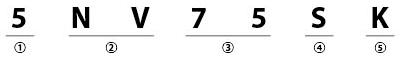
| ① | 取付角寸法 Motor Frame Size |
0: 42mm 2: 60mm 3: 70mm 4: 80mm 5: 90mm 6: 104mm | |
| ② | 減速機タイプ Gear Type |
NV: 通常型減速機 UV: 強化型減速機 |
NV: Standard Gear Head UV: Strong Gear Head |
| ③ | 減速比 Gear Ratio |
(例)75: 減速比 10×中間減速比 1:10 |
Gear Ratio of 1:75 10× denotes the decimal gearhead od ratio 1:10 |
| ④ | 形状 | S: スタンダード形状 F: フランジ形状 |
S: Standard Shape F: Mount Flange Shape |
| ⑤ | 取付穴 | K: 貫通穴 T: タップ付 |
K: Through Hole T: Screw |
モータ一般規格
GENERAL SPECIFICATIONS OF MOTORS
1W~180W型、2極・高速型
1W~150W、2P・High Speed
| 項目 Items |
規格 Specifications |
|---|---|
| 絶縁抵抗 Insulation Resistance |
常温・常湿環境下でモータ定格運転後、コイルとケース間をDC500Vメガーで測定した値が100MΩ以上。 In the cicumstance of normal ambient temperature and humidity, the resistance can be up to 100MΩ or more when 500VDC megger is applied between the windings and the frame after rated motor operations. |
| 絶縁耐圧 Dielectric Withstanding |
常温・常湿環境下でモータ定格運転後、コイルとケース間に50Hzまたは60Hz、1.5kV(三相380Vは1.8kV)を1分間印加しても異常ありません。 In the circumstance of normal ambient temperature and humidity, there will be no problem to withstand 1.5kV (three phase 380V: 1.8kV) at 50/60hz between the windings and the frame for 1 minute after rated motor operation. |
| 温度上昇 Temperature Rise |
常温常湿環境下でモータ定格運転後、抵抗法で巻線温度上昇を測定した値が80℃以下(三相は70℃以下)。 The temperature rise of winding are 80℃ or less measured by the resistance change method after rated motor operation under normal ambient temperature and humidity, with connecting a gear head or equivalent heat radiation plate※. |
| 絶縁階級 Insulation Class |
UL/CSA規格: A種(105℃)、EN規格:B種(130℃)、F種(155℃) UL/CSA Standards: Class A (105℃) EN Standards: Class B (130℃), Class F (155℃) |
| 加熱保護装置 Overheat Protection |
加熱保護装置(自動復帰型) ※オプション B種(開放:120℃±5℃、80℃±15℃) F種(開放:145℃±5℃、95℃±15℃) Thermal Protector inside (automatic return) opening: Class B (opening 120℃±5℃, 80℃±15℃) Class F (opening 145℃±5℃, 95℃±15℃) |
| 使用環境温度 Ambient Temperature |
単相100V、三相200V:-10~+50℃(結露無き事) 他電圧:-10~+40℃(結露無き事) Single-Phase 100VAC, Three-Phase 200VAC:-10~+50℃ (Nonfreezing) Others: -10~+40℃ (Nonfreezing) |
| 使用環境湿度 Ambient Humidity |
85%以下(結露無き事) 85% or less (Noncondensing) |
| 保護等級 Protection Class |
リード線型:IP20 Lead Wire Type:IP20 端子箱型 Terminal Box Type 単相 Sinble-phase 100V50/60Hz、110/120V60Hz、220/230V50Hz、220/230V60Hz 25W~180W IP54 三相 Three-phase 220/220/230V50/60Hz、380/400/415V50/60Hz 25W~180W IP54 |
放熱板寸法(材質:アルミニウム)
Heat Radiation Plate Dimension (Material: Aluminum)
| モータ分類 Motor Type |
寸法 Size (mm) |
厚み Thickness (mm) |
|---|---|---|
| 1W、3W Type | 80×80 | 5 |
| 6W Type | 115×115 | |
| 15W Type | 125×125 | |
| 25W (2極・高速NV4I40型) (2P/High-Speed NV4I40Type) |
135×135 | |
| 40W、60W Type | 165×165 | |
| 60W、90W、120W (2極・高速NV5I150型) (2P/High-Speed NV5I150Type) |
200×200 | |
| 120W、140W、180W Type | 230×230 |
モータ特性
MOTOR FEATURES
インダクションモータ特性
Induction Motor Features
- 一般的に小型インダクションモータは電磁誘導により回転するモータです。モータの起動・回転にはコンデンサと電磁気が重要になります。起動トルクは大きくありませんが、構造がシンプルで高い効率で連続回転させることができます。
- 単相モータは回転方向を変えることができます。回転方向を変えるときはモータ停止後に切り替えを行ってください。
- 三相モータは三相電源により回転します。高い効率と起動トルク特性を持ち合わせています。
- Generally, Micro Induction Motor refers to the motor rotated by the induction. Induction Motor relies on capacitor and electromagnetism when starting and rotating. Though it's stating torque is not very high, it has a simple structure, high efficiency and can rotate continue.
- The single-phase motor have a reverse direction with the rotating's when operated. Please change the direction of single-phase motor rotation only after bring the motor to a stop.
- Three-phase motor relies on three-phase supply. It has a high efficiency and can get a high starting torque.
レバーシブルモータ特性
Reversible Motor Features
- レバーシブルモータは回転方向を頻繁に変えることが出来るようにモータ後端に簡易ブレーキを内蔵しています。簡易ブレーキの構造はブレーキ板にブレーキシューをコイルスプリングによる常時圧力で摺動させます。簡易ブレーキの働きは右記のようになります。(参照:図1)
- 簡易ブレーキの保持トルク・オーバーランについては下表をご覧ください。ご使用の環境により数値が異なる場合がありますのでご注意ください。
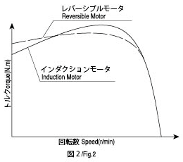
- レバーシブルモータはインダクションモータのようにコンデンサにより起動し同様の特性を有しています。瞬間的な回転方向切り替えに対応出来るように高い起動トルク特性が有ります。(参考:図2)
- 負荷摩擦により瞬間可逆性の向上
- オーバーランの縮小
- 一程度の保持力維持(定格トルクの10%程度)
- With friction load, increasing the instant reversal.
- Shorten over-run.
- Keep the torque in some way. (about 10% of the rated torque)
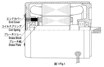
- Reversible Motor has a friction brake at the back of the motor body, which is designed for applications where reversal of direction is frequently required. For the friction brake, please check Draw 1. The damp with spring impacts the rotating brake disk and supplies with continuous press. The functions of the friction brake are as following:
- The keeping torque or more of the friction brake and over-run are listed in the table 1. It is only for reference. As it will change according to the rotating period as well as the temperature. Please also note that the Torque may be a little lower than the one listed in the table when being operated initially.
- The reversible Motor, like Induction Motor, is started by the capacitor and has a same torque characteristic with the Induction Motor. But the Reversible Motor is designed with a higher starting torque to increase the instant reversal features. Please check drawing2.
保持トルク・オーバーラン表
Table 1. Keep Torque and Over-run
| 相数 Phase |
寸法 Size |
出力 Output |
モータ型番 Motor Model |
保持トルク Keep Torque |
オーバーラン Over-run |
|
|---|---|---|---|---|---|---|
| mm | W | N.cm | Kgf.cm | 回転数 Cycles |
||
| 単相 Single-phase |
60 | 6 | NV2R6 | 0.5 | 0.051 | 4 |
| 70 | 15 | NV3R15 | 1.3 | 0.133 | 5 | |
| 80 | 25 | NV4R25 | 1.5 | 0.153 | 5 | |
| 90 | 40 | NV5R40 | 4.0 | 0.40 | 6 | |
| 60 | NV5R60 | |||||
| 90 | NV5R90 | |||||
| 120 | NV5R120 | |||||
無励磁作動型電磁ブレーキ付モータ特性
Power Off Activated Type Electromagnetic Brake Motor Features
-
動作構造
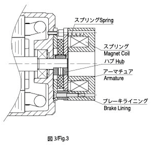
無励磁作動型電磁ブレーキ付モータはコイルに電圧をかけるとスプリングにより押されていたアーマチュアが吸引されます。そしてアーマチュアとブレーキライニングの間に間隙が発生してモータが回転します。コイルの電圧を切ると、アーマチュアとスプリングによりブレーキライニングに圧力をかけることにより制動力が発生しモータは停止します。(注:図3)
-
電磁ブレーキ特性
交流による無励磁作動型電磁ブレーキで、モータとダイレクトに接続されています。電力解除と同時にモータ瞬時停止し負荷を保持します。保持トルクは0.05~2.0N・mです。電力解除後に保持力を有する構造となっており、予期せぬ電力解除時の安全ブレーキとして適しています。頻繁な回転方向の切り替えができ、1分間に6回程度の停止ができます。(3秒以上の間隔を開けてご使用ください。)
モータとブレーキ部には同じ電源・交流電源を用いることができます。上記数値はご使用環境によって必ずしも同じとは限りません。ご使用の際はモータケース表面温度が90℃以下となるようにご注意ください。
-
起動時間・制動時間特性
電磁ブレーキ付モータの起動時間は、モータの起動時間に電磁ブレーキ解放時間を加えたものです。制動時間は電力解除後にモータが完全に停止するまでの時間となります。モータ起動時間、制動時間やオーバーランはご使用機器の組み合わせや環境により異なりますのでご注意ください。
-
Structure and Operation Principle
Table 3 is the structure for the Electromagnetic Brake Motor. We produce the Power Off Activated Type. Exerting the voltage on the winding, it will magnetize the armature pressed by the spring. The motor will be in a stage of rotating, when there is a backlash between the armature and brake rim. Once the winding voltage is cut down, under the influence of spring, the armature press the brake rim, which will create a brake force. Then the motor gets to a stop.
-
The Characteristics of the Electromagnetic Brake
It is an AC Power Off Activated Type Electromagnetic Brake which is connected directly with the motor. It will get to a blink stop and keep load when the supply is power off. It will keep the torque between 0.05-2.0Nm. It is especially suitable for the safety brake in the circumstance of unconsciously power off. The electromagnetic can change its direction frequently. It can be stopped 6 times in a minute. But be sure that it lasts for 3seconds or more.
After we set a commutating loop in the brake, it can share the power supply with the motor.
The value is standard. It will be change in different condition. When actually used, be sure to make the surface temperature of the motor less than 90℃.
-
The Features for the Starting Time and Brake Time
The starting time means the time for the motor's starting time plus the electromagnetic brake release time. The brake time means the time from power cut off to the time of motor completely stop. The over-run, starting time and brake time will be different according to the different applications.
電磁ブレーキ特性(無励磁作動型)
Electromagnetic Brake (Power off Activated)
| 相数 Phase |
寸法 Size mm |
出力 Output W |
電圧 Voltage V |
周波数 Frequency Hz |
電流 Current A |
出力 Output W |
保持トルク Keep Torque N.m Kgf.cm |
オーバーラン Over-run 回転数 Cycles |
|
|---|---|---|---|---|---|---|---|---|---|
| 1 Phase | 70 | 15 | 100 110 120 |
50/60 | 0.191 | 8.2 | 0.5 | 5 | 3.5 |
| 80 | 25 | ||||||||
| 90 | 40 | ||||||||
| 60 | |||||||||
| 90 | 220 230 |
0.111 | 10.0 | 1.0 | 10 | ||||
| 120 | |||||||||
| 100 | 120 | ||||||||
| 140 | |||||||||
| 180 | 0.144 | 13.0 | 2.0 | 20 | |||||
| 3 Phase | 60 | 6 | 200~230 | 50/60 | 0.073 | 6.6 | 0.25 | 2.5 | |
| 70 | 15 | 380~415 | 0.037 | 6.6 | 0.25 | 2.5 | |||
| 80 | 25 | 200~230 380~415 |
0.091 0.046 |
8.2 8.2 |
5.0 5.0 |
5 5 |
|||
| 90 | 40 | ||||||||
| 60 | |||||||||
| 90 | 200~230 380~415 |
0.111 | 10.0 | 1.0 | 10 | ||||
| 120 | |||||||||
| 100 | 120 | 0.056 | 10.0 | 1.0 | 10 | ||||
| 140 | |||||||||
| 180 | 200~230 380~415 |
0.144 | 13.0 | 2.0 | 20 | ||||
| 0.072 | 13.0 | 2.0 | 20 | ||||||
スピードコントロールモータ
The Features of the Speed Control Motor
- モータとコントローラのセットで使用し簡単に接続ができます。スピードはポテンションメータにより簡単に調整が可能です。モータを瞬時停止させる機能はついておりません。
- コントーラにより以下の範囲でスピードの調整が出来ます。 50Hz:90-1400rpm 6Hz:90-1700rpm
- 過度の温度上昇を避けるためにモータを長時間低速状態でご使用にならないでください。
- It is a unit of the controller and motor. It only needs to connect one time. The speed can be easily adjusted by the potentiometer. The controller is fixed with speed-control loop, capacitor, speed enactment etc. There is no function of instant stop in the unit.
- The controller can make the speed variable between 90-1400rpm at 50 Hz and 90-1700rpm at 60Hz.
- Please don't run motor at low speed for long time avoiding over heat.